Capillary tubes function as fixed orifice expansion devices within HVAC systems, allowing for the passive reduction of pressure in liquid refrigerant. When high pressure refrigerant flows into these narrow tubes (usually around 0.5 to 2 mm thick), the resistance created against the walls causes a gradual pressure drop. What happens next is pretty interesting - the subcooled liquid gets transformed into a mix of vapor and liquid at lower pressure and temperature, which makes it ready to absorb heat efficiently in the evaporator part of the system. One big advantage here is that there are absolutely no moving components involved. This mechanical simplicity has proven to work well over time, something that many technicians have observed firsthand during their field experience with various HVAC installations.
Small air conditioning units depend completely on the physical shape of the capillary tube for controlling refrigerant flow. The amount of refrigerant passing through really depends on how long and wide the tube is. If someone makes the tube 20% longer, they'll typically see about a third less refrigerant moving through because there's just more friction happening inside. When tubes get too narrow, they create similar kinds of resistance problems as those fancy mechanical expansion valves do. What's interesting about these simple designs is how they automatically adjust when pressures change within the system. Take warmer outside temperatures for instance. As it gets hotter, the condenser pressure goes up, and this actually causes more refrigerant to flow through the capillary tube all on its own, no need for any complicated electronics or sensors to manage it.
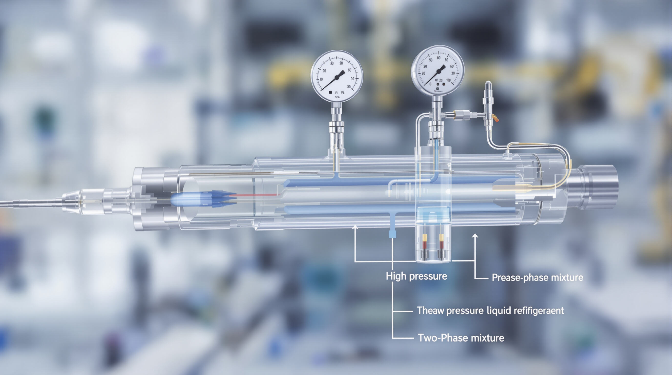
When refrigerant moves through the capillary tube, it experiences quite a big pressure drop, sometimes over 100 psi, during its transition from liquid state to that mix of liquid and vapor we call a two phase mixture. Most of this pressure loss happens right at the beginning actually around 90% occurs within the first third section of the tube itself. By the time it reaches the evaporator inlet, pressures usually settle somewhere between 60 and 80 psi for standard refrigerants like R-410A or similar ones commonly used today. The way the fluid flows basically follows this formula Q is proportional to delta P multiplied by D to the fourth power divided by L. Here, D stands for the inner diameter of the tube while L represents its overall length.
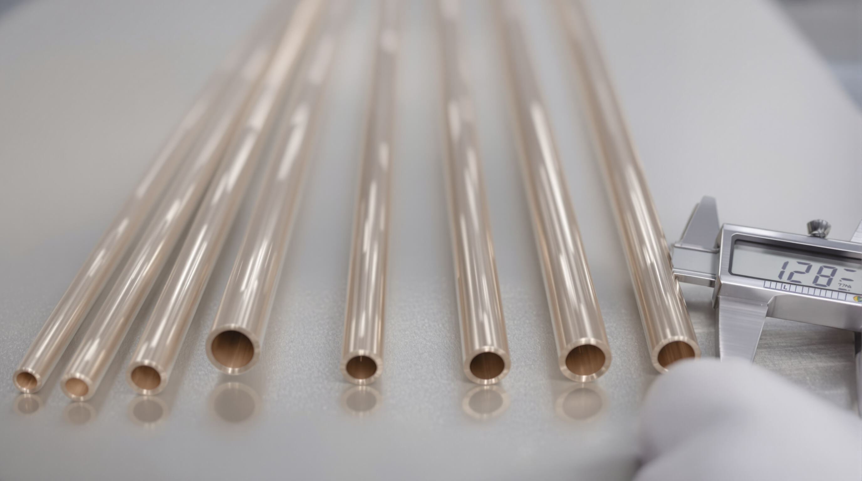
The performance of capillary tubes really depends on getting the geometry right. When tubes get longer, they create more resistance which cuts down on how much refrigerant flows through them. Bigger diameter tubes let more stuff pass through though. Getting these measurements wrong leads to problems either way pressure drops too little or uses way too much energy. This matters a lot for those tiny AC systems with capillary tubes because there's just not much room to work with. Even small changes in dimensions matter a whole lot when space is tight. To get things working properly, technicians need to measure down to the millimeter level so everything matches up with what the system needs for capacity and efficiency.
The inner diameter along with the tube length plays a major role in determining how much pressure drops occur between the condenser and evaporator components. When looking at actual numbers from ASHRAE's 2022 fundamentals report, we find that increasing the diameter by just 0.5 mm leads to roughly 40% better flow capacity. On the other hand, adding another meter to the tube length generally results in pressure drop increases somewhere between 15% and 22%. Most engineers working on these systems tend to adjust diameters first when making broad flow changes, then get into the finer details by tweaking lengths. This approach helps them achieve better subcooling effects while keeping the whole system running smoothly without unexpected fluctuations.
Excessively long tubes reduce evaporator pressure, increasing compressor work, while oversized diameters raise floodback risk due to liquid slugging. Peak system COP is achieved when pressure drop is maintained between 1.8–2.5 MPa and matched with appropriate saturation temperature differentials.
Engineers use two primary approaches: empirical charts that correlate refrigerant flow with pressure differentials, and analytical models incorporating dimensionless numbers like Reynolds and Mach. Modern design increasingly relies on computational fluid dynamics (CFD), which achieves up to 97% accuracy in predicting mass flow compared to traditional sizing methods.
The mass flow rate in those smaller air conditioning units depends on several factors including the shape and size of the tubes, what kind of refrigerant is being used, and the difference between pressures inside the system. Looking specifically at R134a systems, if there's an increase of just 1 bar in the inlet pressure, this tends to boost the overall flow rate somewhere between 18 to 22 percent according to the ASHRAE Handbook from 2006. When we talk about choked flow conditions, these happen when the pressure coming out falls down to around 35 to 40 percent of what was going in, which then stops the flow from increasing further. To give some concrete numbers, take a look at a typical setup where someone might install a tube with a diameter of 1.0 mm and a length measuring about 3.3 meters long. Under normal operating conditions with 15 bars of pressure applied, such a configuration would deliver approximately 16 kilograms per hour worth of refrigerant through the system. Technicians working on these systems need to keep all these relationships in mind during installation and maintenance work.
Inlet phase significantly affects performance. Subcooled liquid entry supports 35% higher flow rates than two-phase mixtures due to reduced vapor formation and associated losses. For example:
Premature vaporization within the tube causes pressure fluctuations (2–3 bar), reducing stability. Flow modeling studies confirm that maintaining at least 8K of subcooling prevents early vaporization in 89% of small AC applications.
After an initial metastable liquid phase, rapid expansion accelerates in the final third of the tube, where temperature gradients can exceed 50°C/m. This underscores the importance of accurate refrigerant charging and system design.
Capillary tubes play a key role in vapor compression systems by acting as fixed orifice expansion devices that connect the high pressure condenser section to the low pressure evaporator part of the system. When refrigerant flows into these narrow tubes, there's a sudden drop in pressure which causes flash evaporation to occur. What happens here is pretty interesting actually the high pressure subcooled liquid gets transformed into a cooler saturated mixture that can then absorb heat effectively within the evaporator component. One big difference between capillary tubes and thermostatic expansion valves is that these tubes don't need any sensors or moving components at all. This makes them especially good for applications where maintenance needs to be minimal and systems are completely sealed off from external interference.
Capillary tubes are widely used in cost-sensitive, fixed-load applications due to their reliability and simplicity. Common systems include:
The small ac capillary tube design is especially effective in compact installations where space and reliability are paramount. These systems typically operate below 5 tons and perform best under stable ambient conditions. Their self-compensating nature allows adaptation to minor load changes without electronic controls, enhancing durability in permanent sealed systems.
Capillary tubes bring some real benefits when it comes to smaller HVAC systems. Since there are absolutely no moving components involved, this means no mechanical wear happens over time which cuts down on both maintenance needs and breakdowns. The fact that these tubes take up so little space makes them easy to fit into cramped installations too. Plus their ability to regulate fluid flow pretty accurately helps maintain steady system performance across different conditions. A recent report from 2024 looking at HVAC reliability showed something interesting actually - systems using capillary tubes had around 32 percent less service calls for issues with expansion devices than those relying on electronic versions instead.
Capillary tubes adjust refrigerant flow on their own when there are changes in system load. When the evaporator has higher loads, the pressure difference increases which pushes more refrigerant through the tube. Conversely, when loads drop off, the flow just naturally decreases without any outside intervention. What makes these tubes so useful is that they maintain stable operation throughout all this without needing any fancy sensors or control systems. There is one catch though. Because capillary tubes have fixed dimensions, they don't perform well in situations where load variations exceed around 40% above or below what was originally designed for. This limitation means operators need to be careful about matching application requirements to tube specifications.
Selecting the right capillary tube involves balancing three key factors:
Getting the right material combinations matters a lot these days, particularly when working with newer refrigerants such as R-454B or R-32. Standard copper tubing works fine for many regular refrigerants out there, though sometimes it needs a layer of nickel coating if we're dealing with those ammonia based solutions. When materials don't match up properly, things start breaking down over time both inside the tubes themselves and within the refrigerant mixture. According to research from ASHRAE back in 2023, this mismatch can actually cut system efficiency down by nearly 19%. So picking compatible materials isn't just good practice, it's really what keeps systems running reliably year after year while maintaining their thermal performance capabilities.


 Hot News